At long last it is time to tell the tale of the electrical cabinet! I started working on this back in mid June almost as soon as I got the batteries, inverter and charge controller.
Originally, I’d planned to have most of the electrical equipment neatly tucked under counters or benches and was thinking up some nifty forced air schemes for keeping everything ventilated while still having it as out of the way as possible. That all changed when I started looking into the mounting requirements for the inverter.
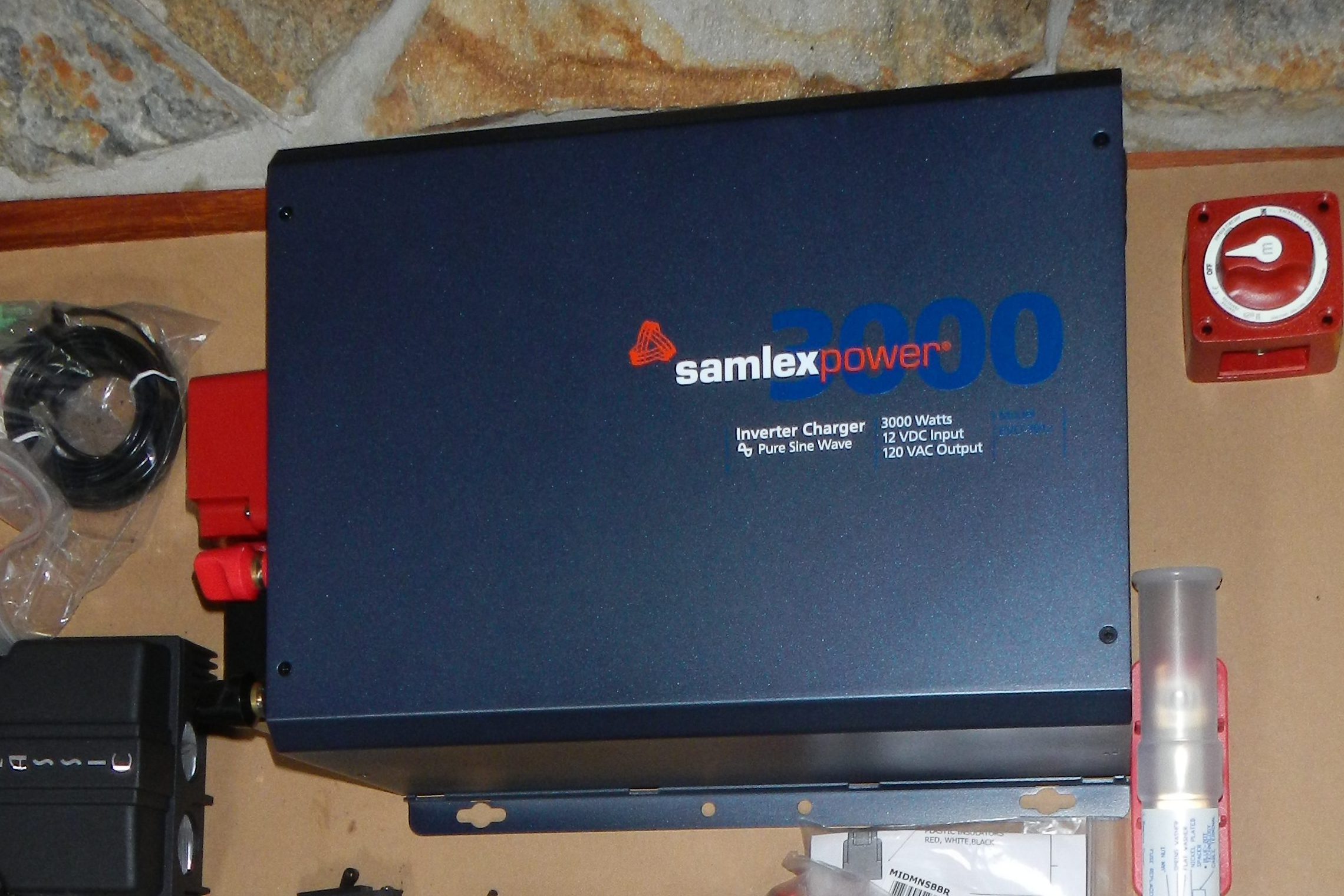
Inverters come in two types: high frequency and low frequency. Most retail inverters are high frequency, and have multiple small transformers. They are lightweight, and are fine for running lightweight loads, but do not handle surge loads (such as those from electric motors) well at all.
Low frequency inverters have a single massive transformer which is quite capable of powering surge loads. They also tend to be more efficient and run cooler. These are good qualities, but that massive iron core transformer comes at the cost of weight.
The Samlex EVO I purchased is aimed at stationary or marine installations, and the documentation states that it should not be installed in a vessel less than 65 feet in length due to the increased risk of vibration and shock loads.
The bus rides on leaf springs, and the ride quality can be called “firm” if one is feeling charitable. This necessitated a redesign of the electrical system, since I do not want to have the transformer drop out the bottom of the inverter while underway.
My thought process which led to the electrical cabinet in its current incarnation is roughly as follows:
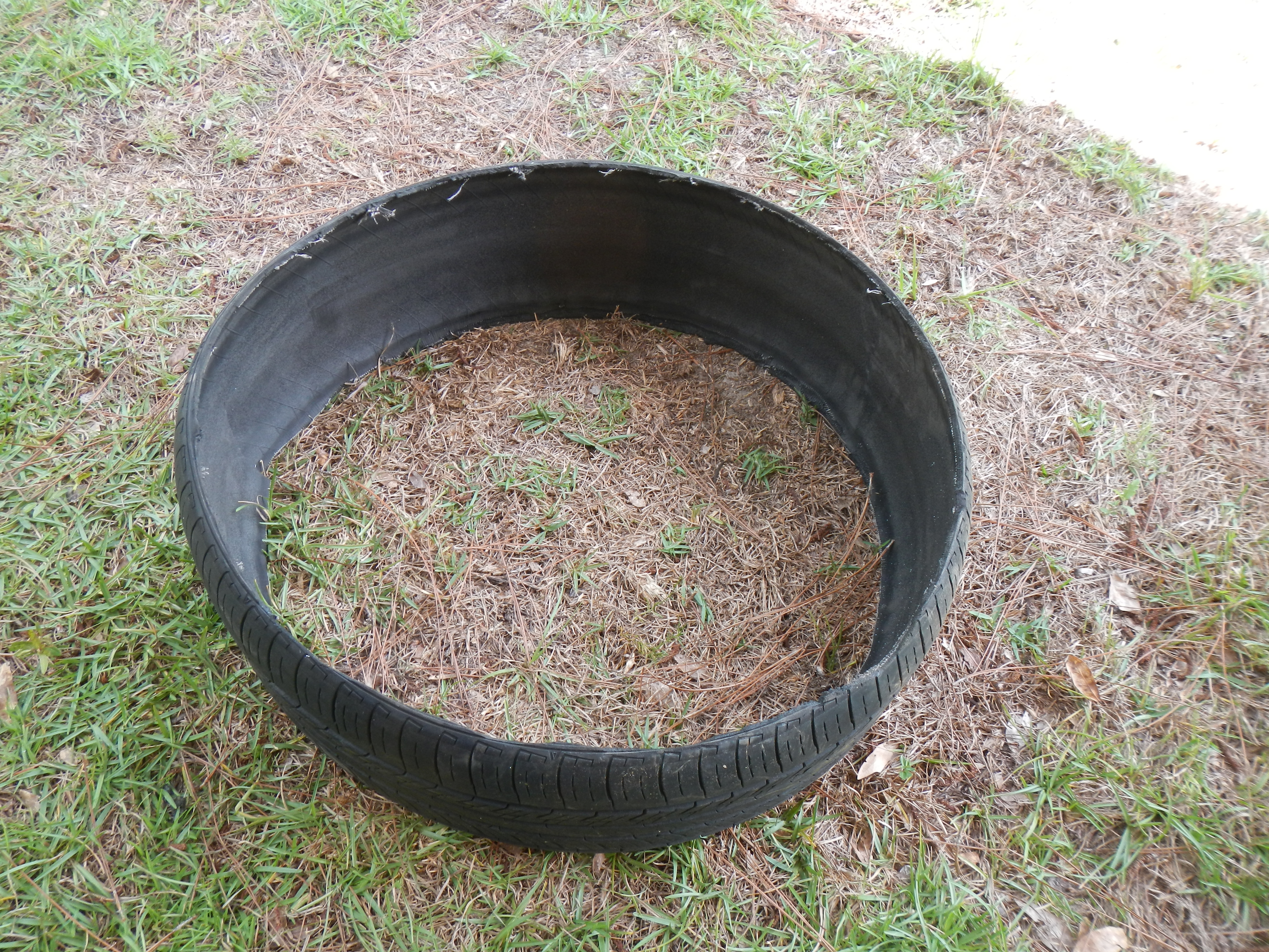
- The only way to really effectively deal with vibration and shock loads is to isolate using some form of suspension
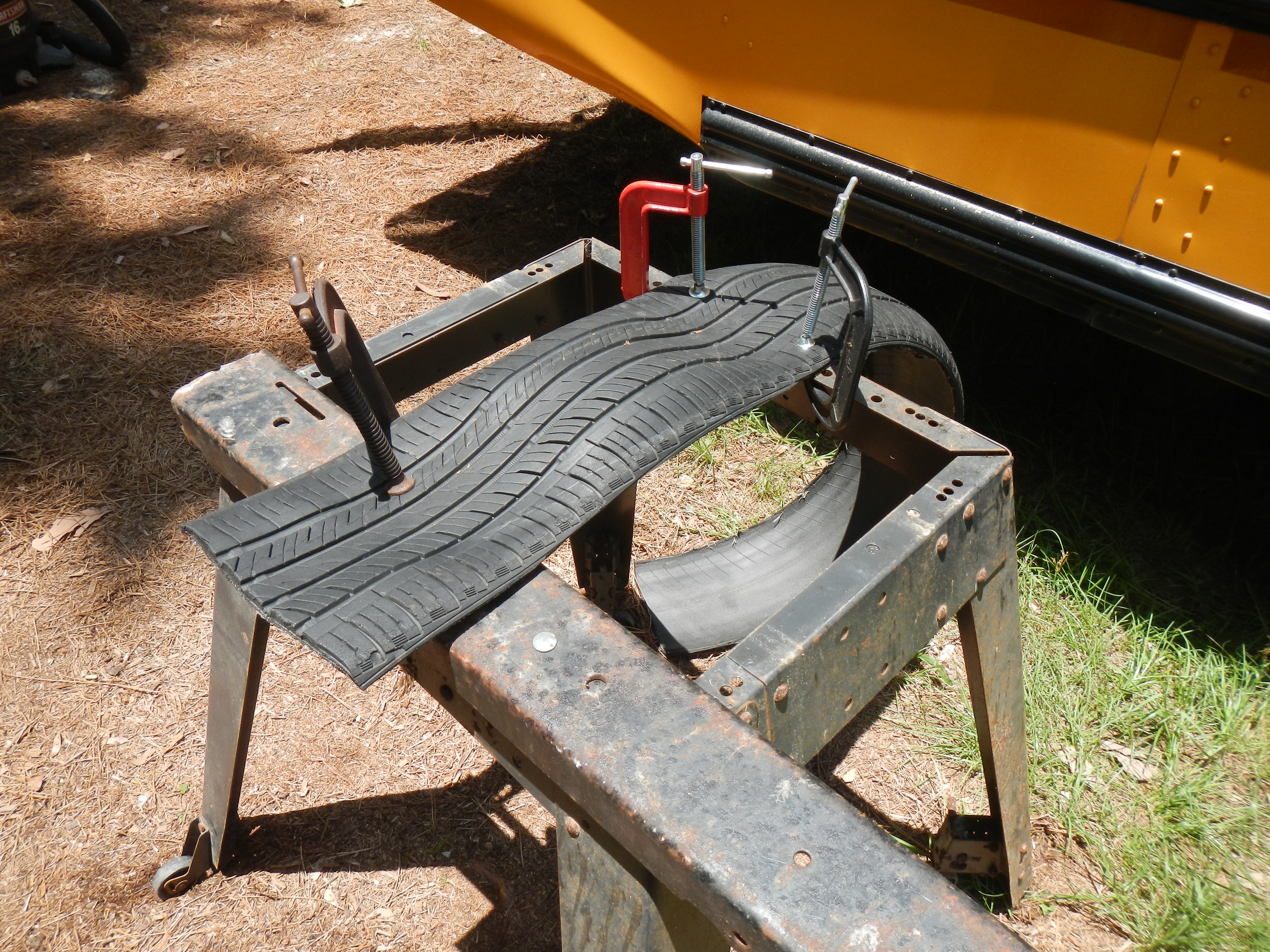
- This suspension needs to have substantial travel with progressive resistance
- One does not want the bulk of the suspended load to be the delicate item itself- the transformer in this case- so we want to add additional mass to the suspended load
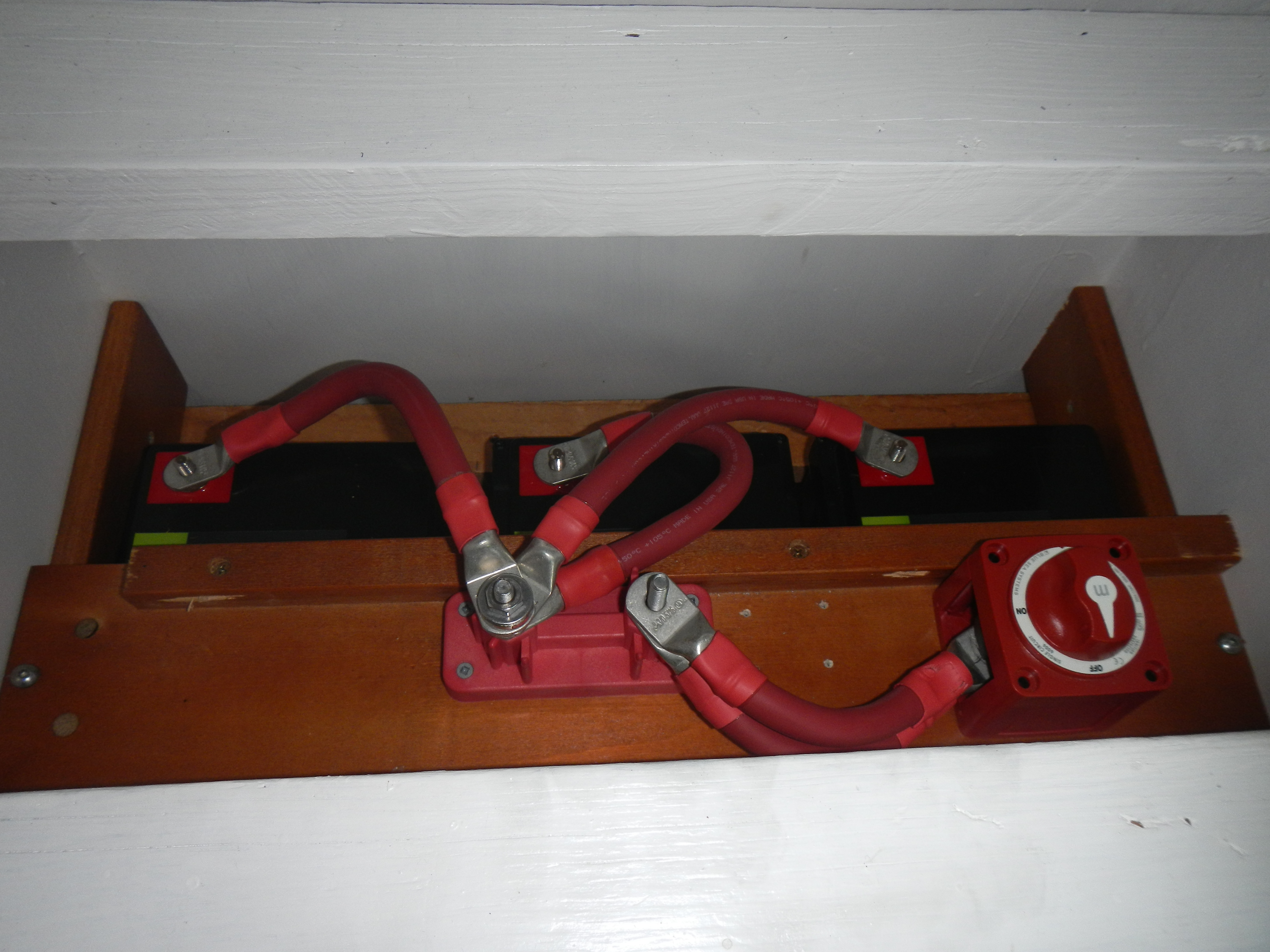
- Batteries have substantial mass, and we want them to be as close to the inverter as possible to minimize wire runs, so they should be added to the suspended load
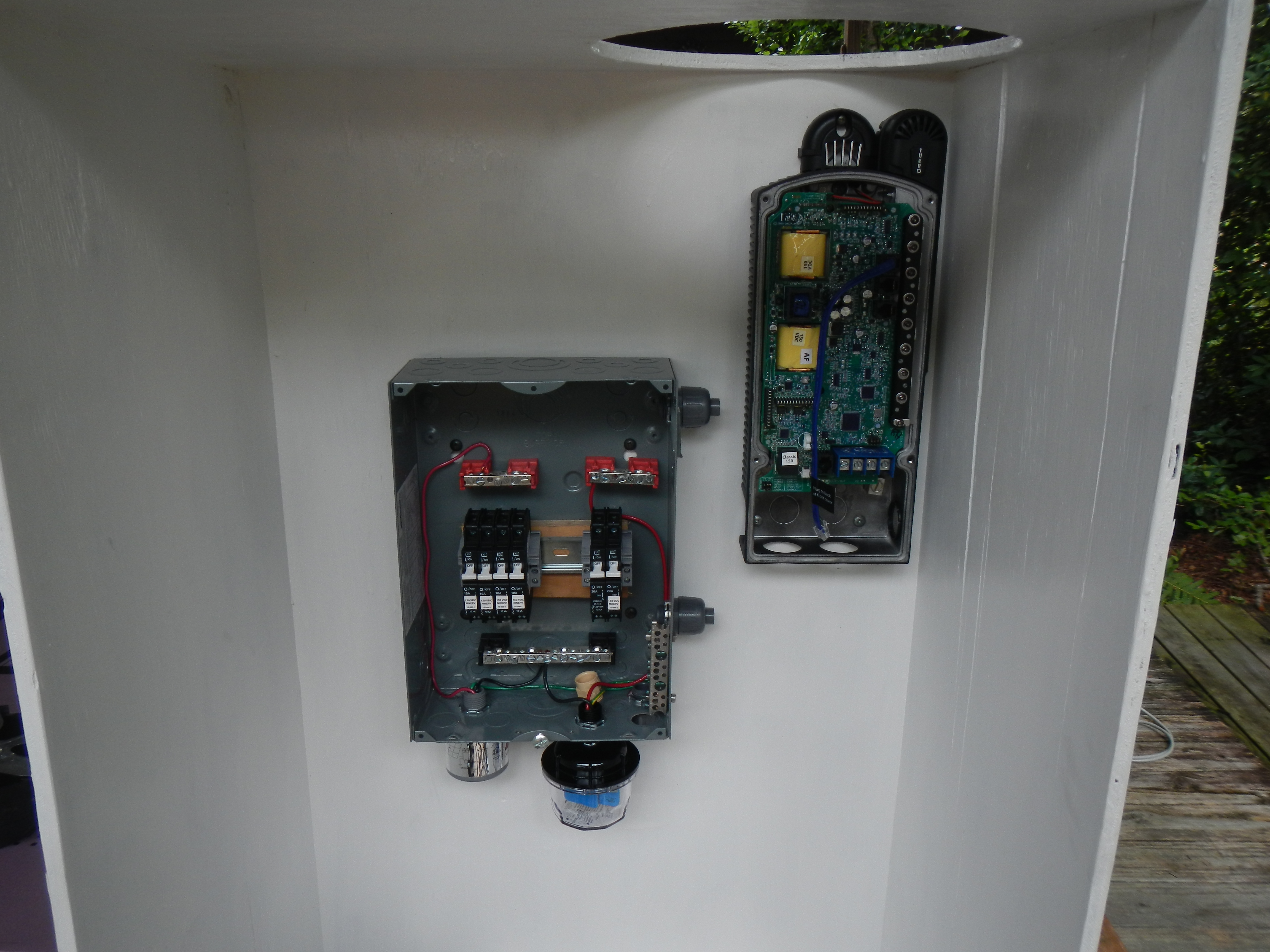
- If the batteries are close, then that means the charge controller should be close as well. Makes sense to add that to the suspended load
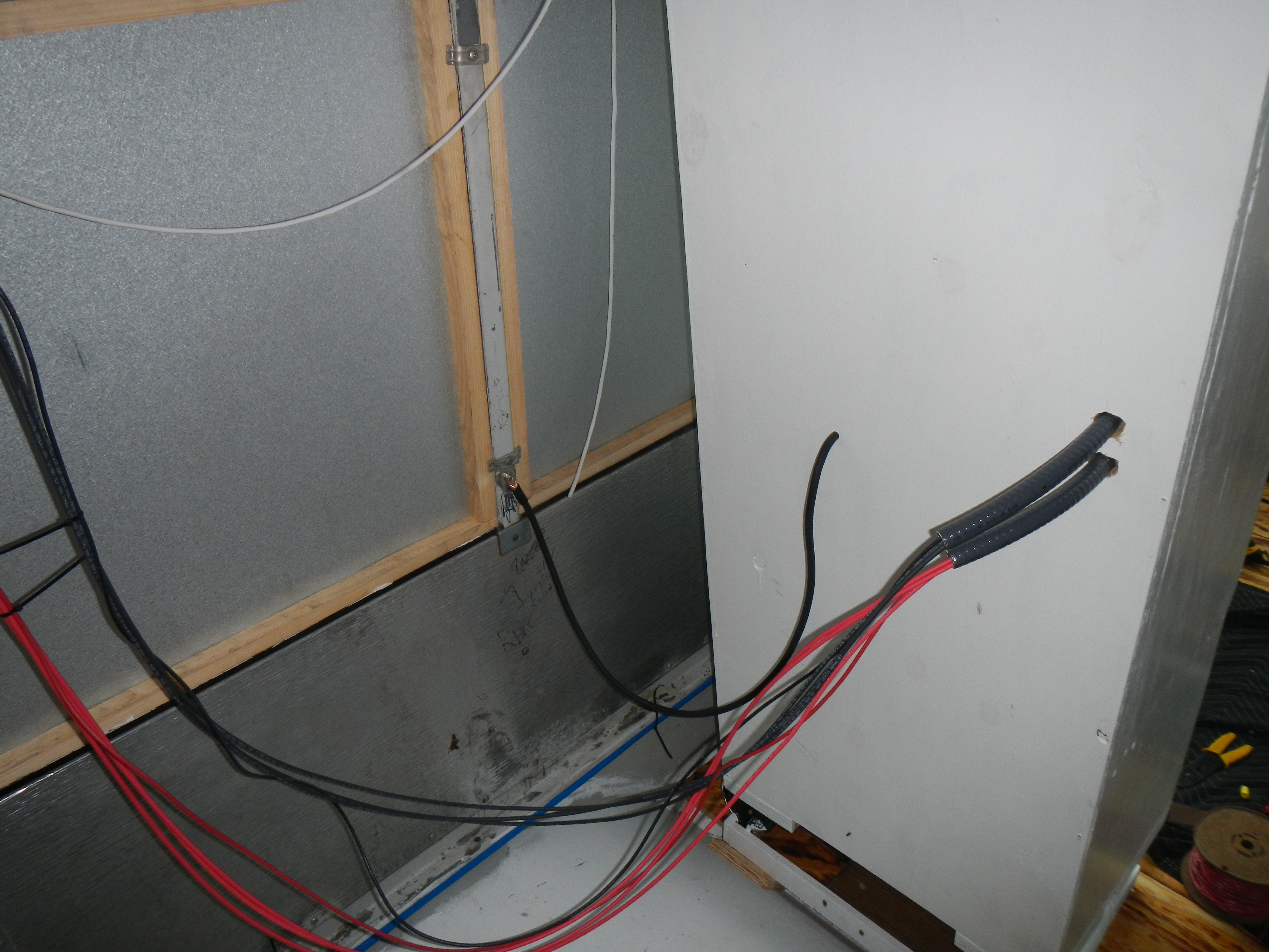
- Any wires which traverse the gap between the suspended load and the bus will be subjected to long term stress in the form of vibration and repeated flexion. It is thus important to minimize the number of wires which must traverse this gap, and to ensure that all wires which do cross the gap are appropriately protected in case of insulation breakdown. This means fuses and breaker boxes must be part of the suspended load
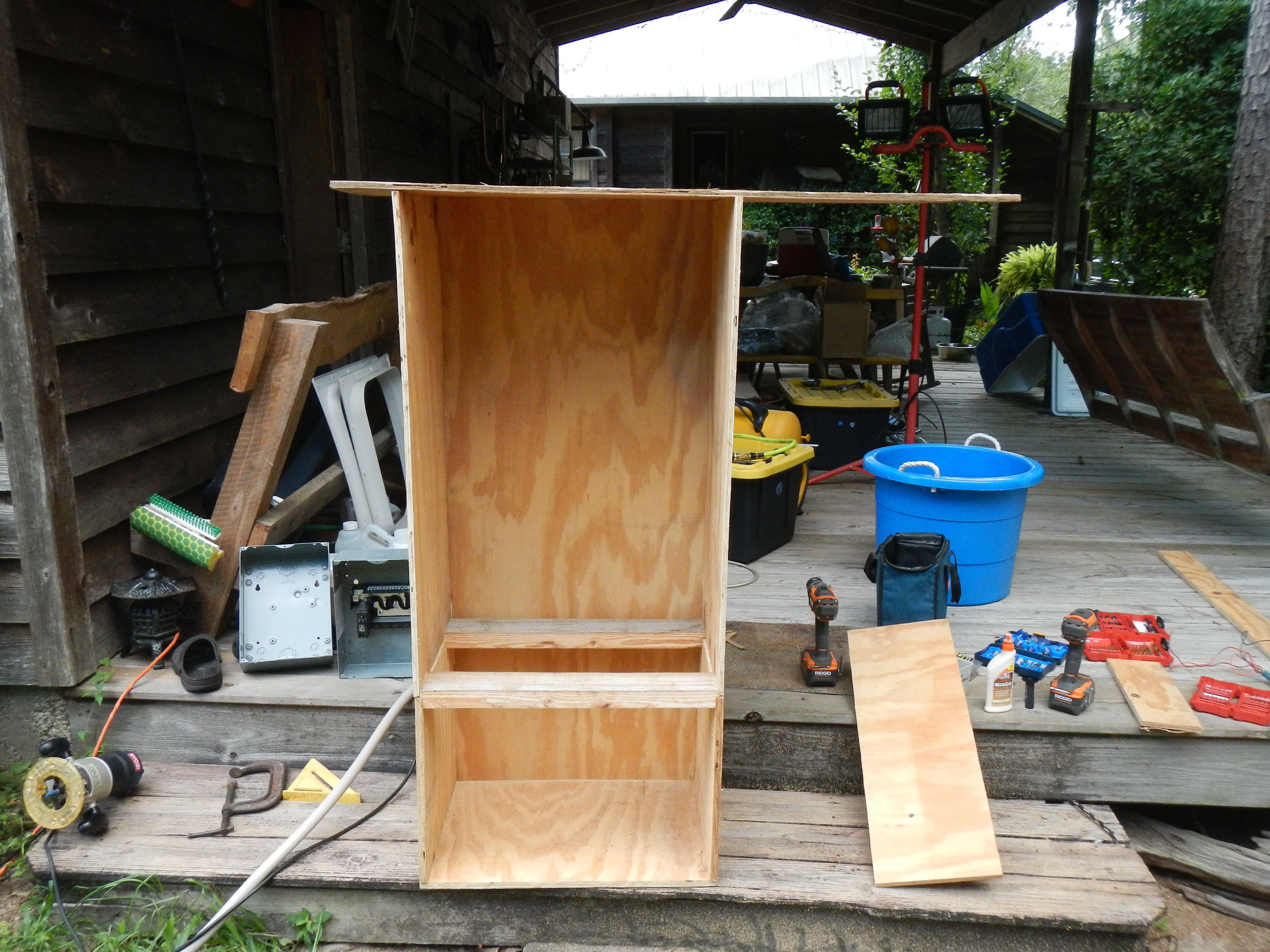
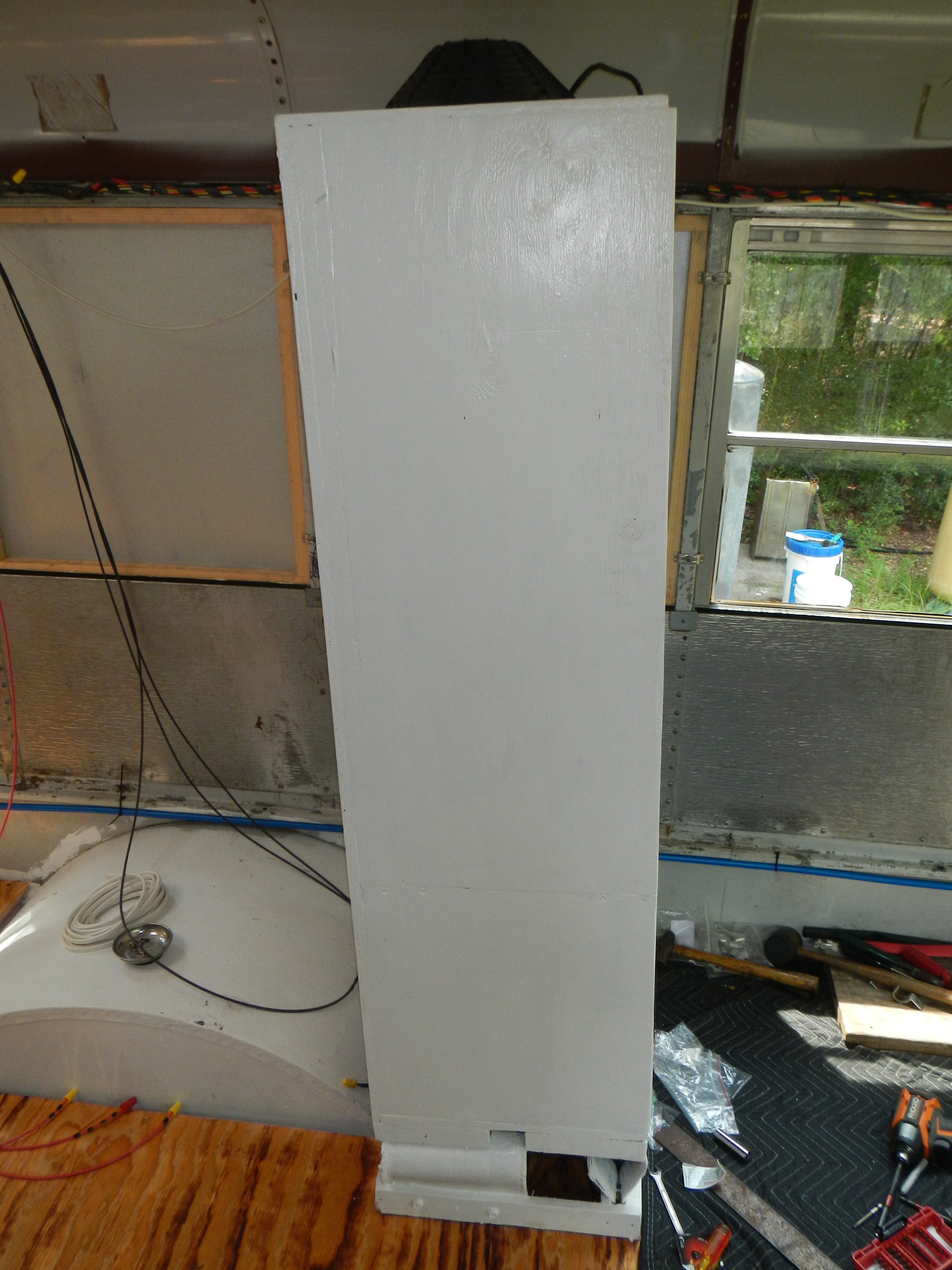
So, it makes sense to have the heart of the electrical system in one enclosure which is isolated from the rest of the bus by some form of shock mounting solution.
I originally considered using a metal enclosure, but everything I could find was some combination of the wrong size and shape, too flimsy, or too expensive.
I attempted to fabricate a metal enclosure using re-purposed material from the bus seats. This went poorly, so I moved on to plan C.
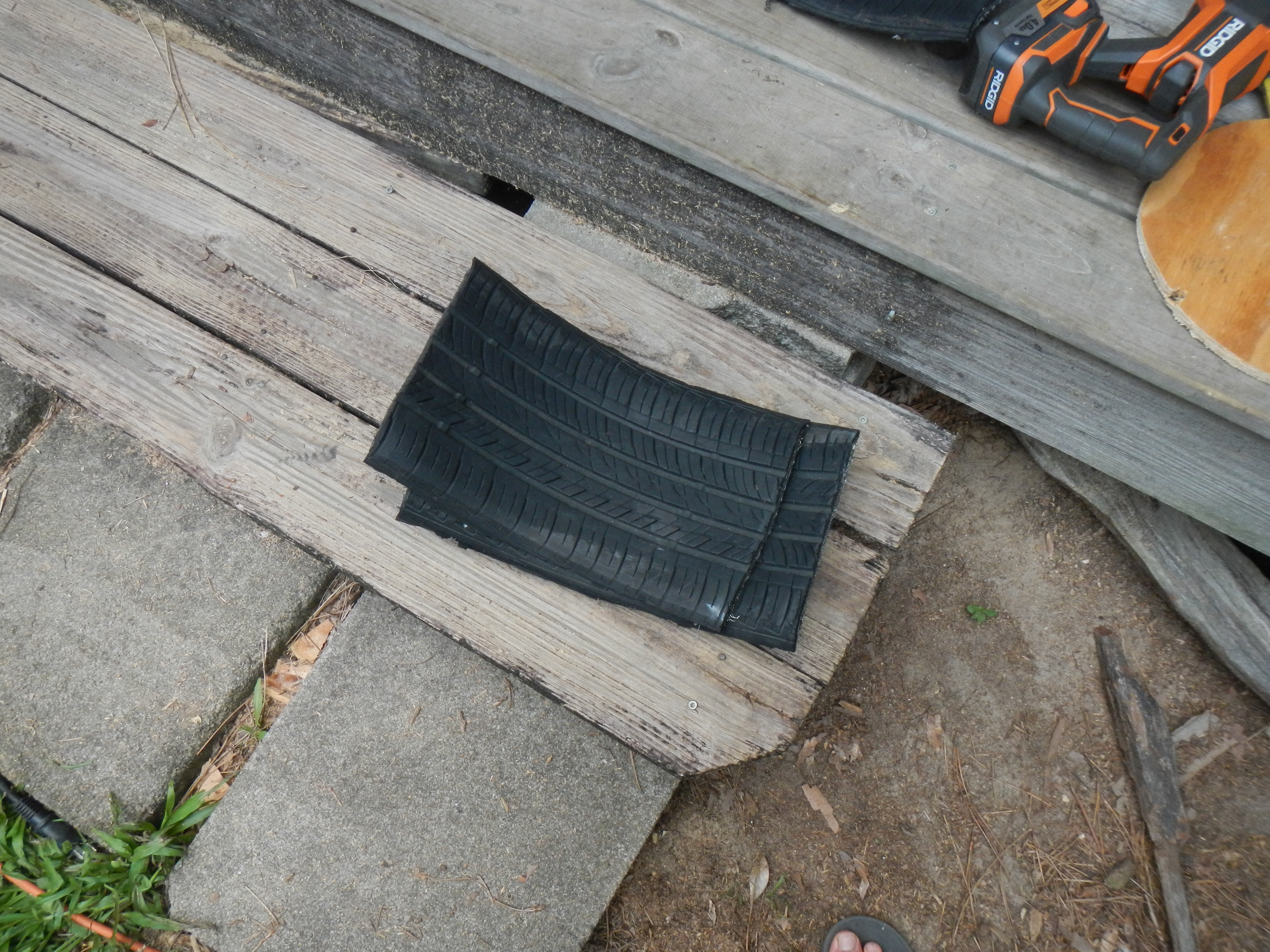
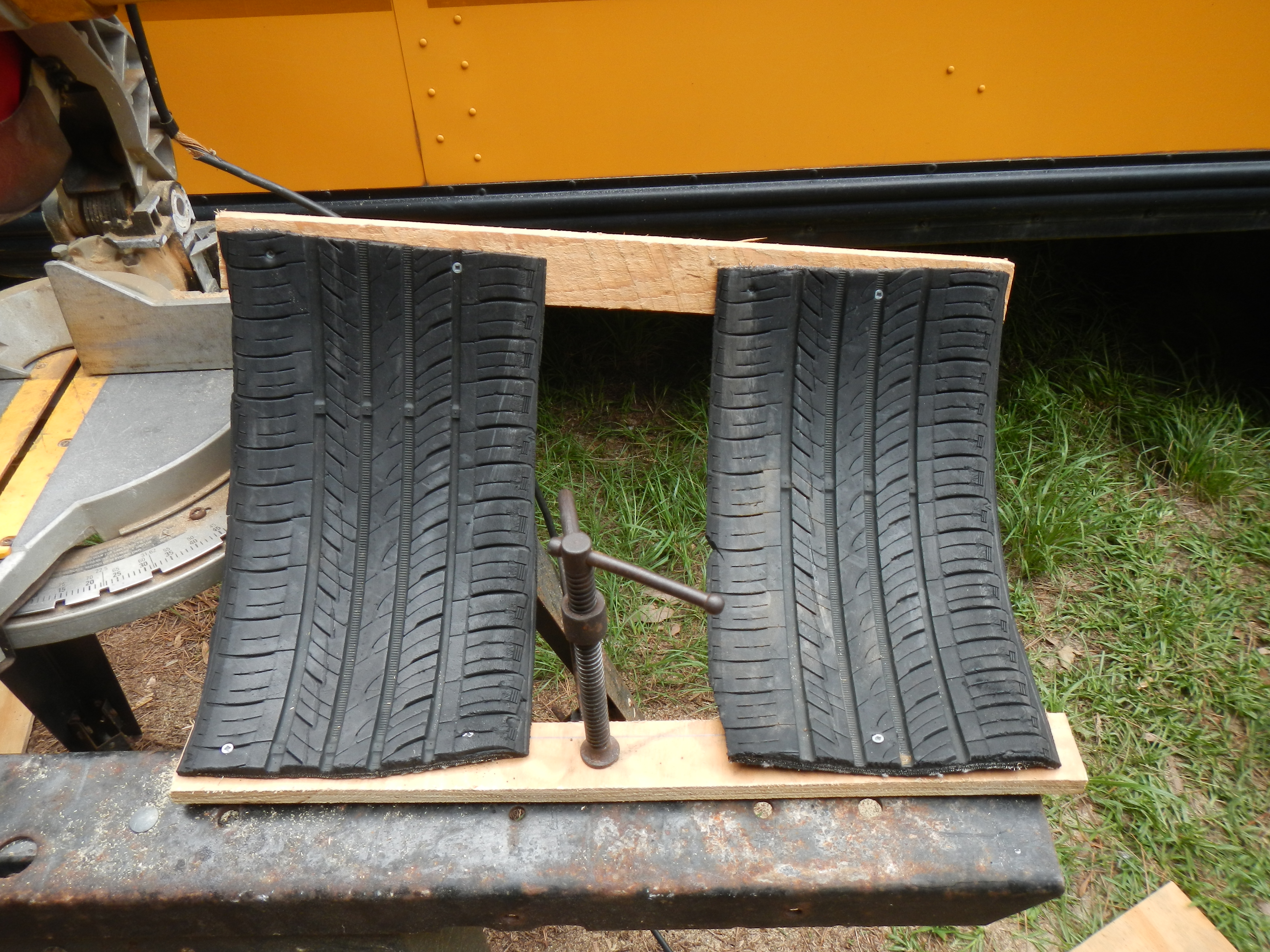
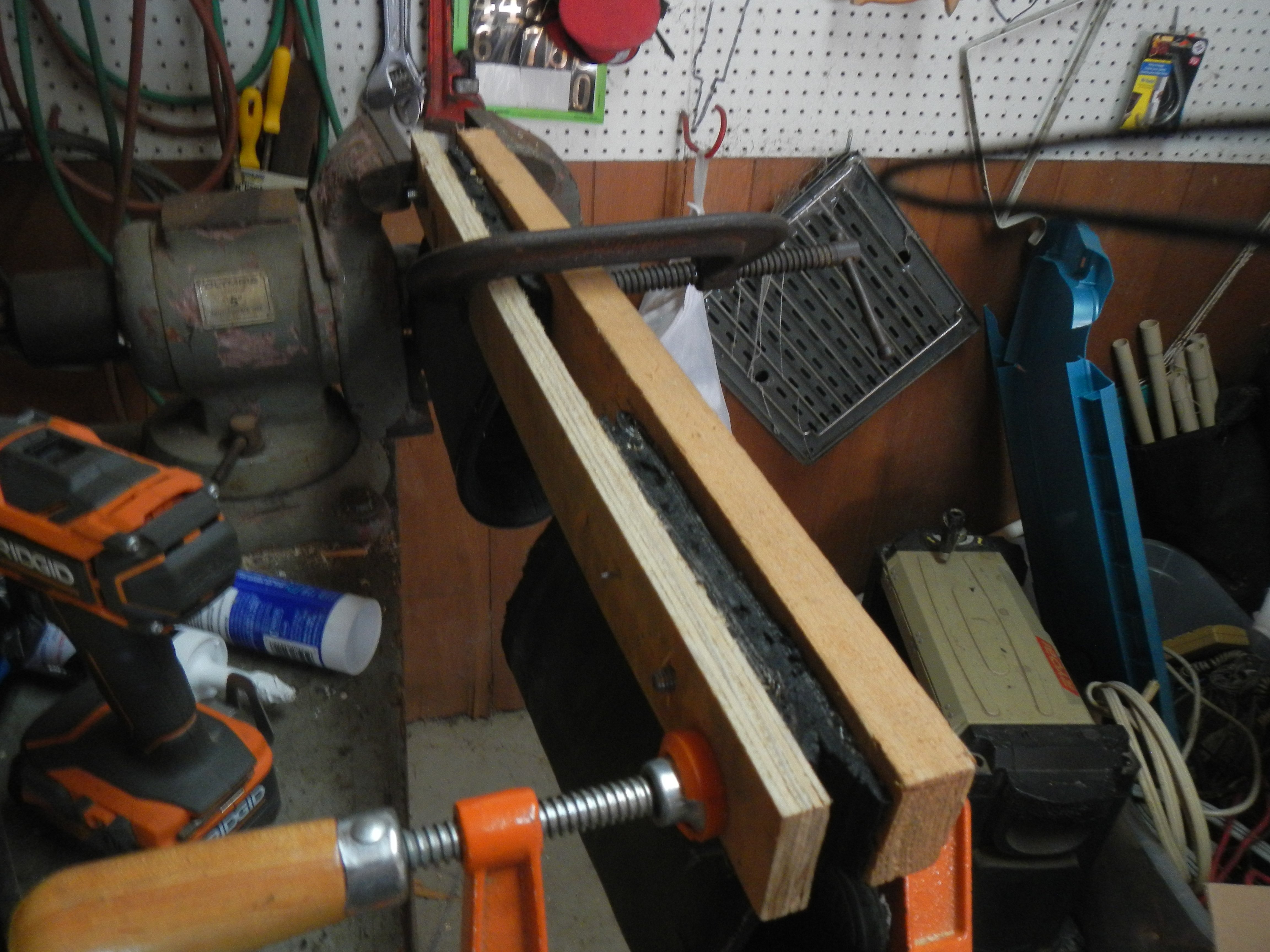
Commercially available shock isolation mounts capable of handling a hundred kilograms or so are tremendously expensive (roughly $500 each) and difficult to find…
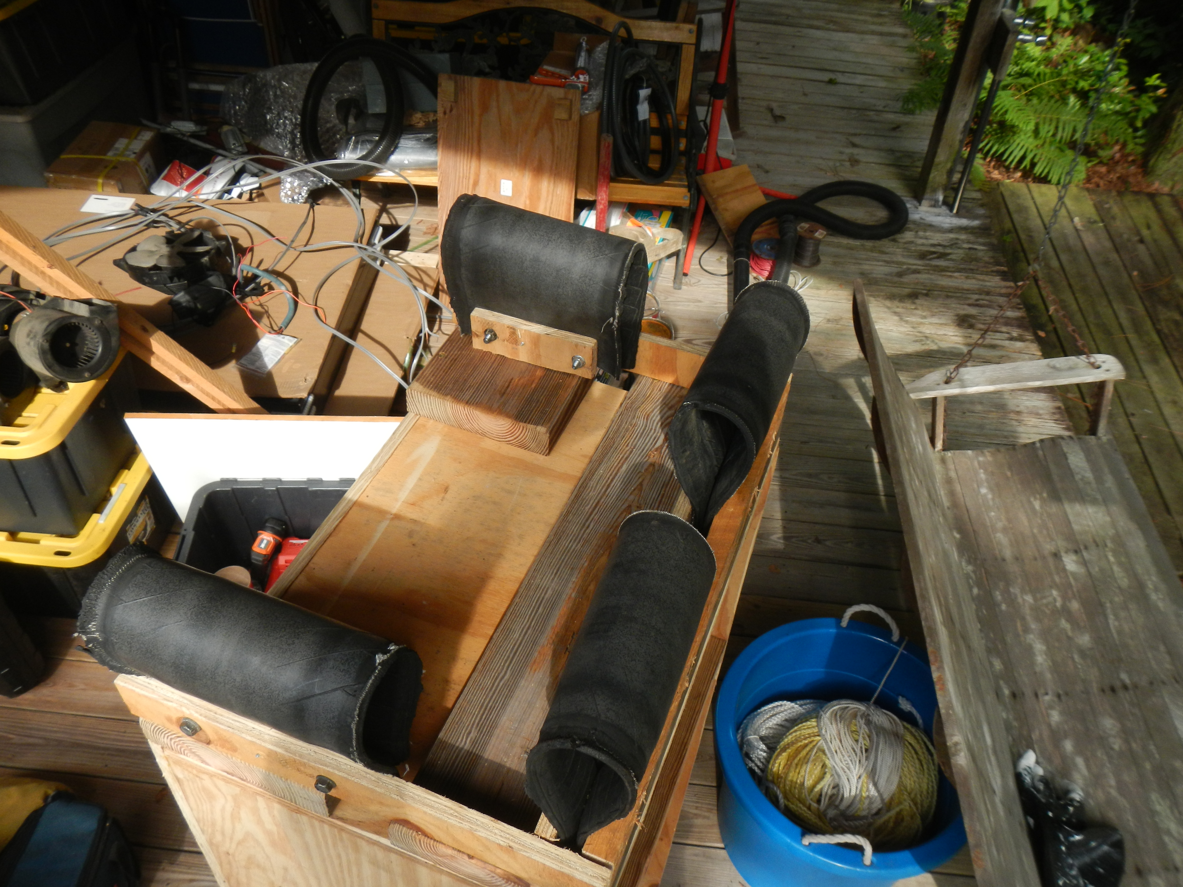
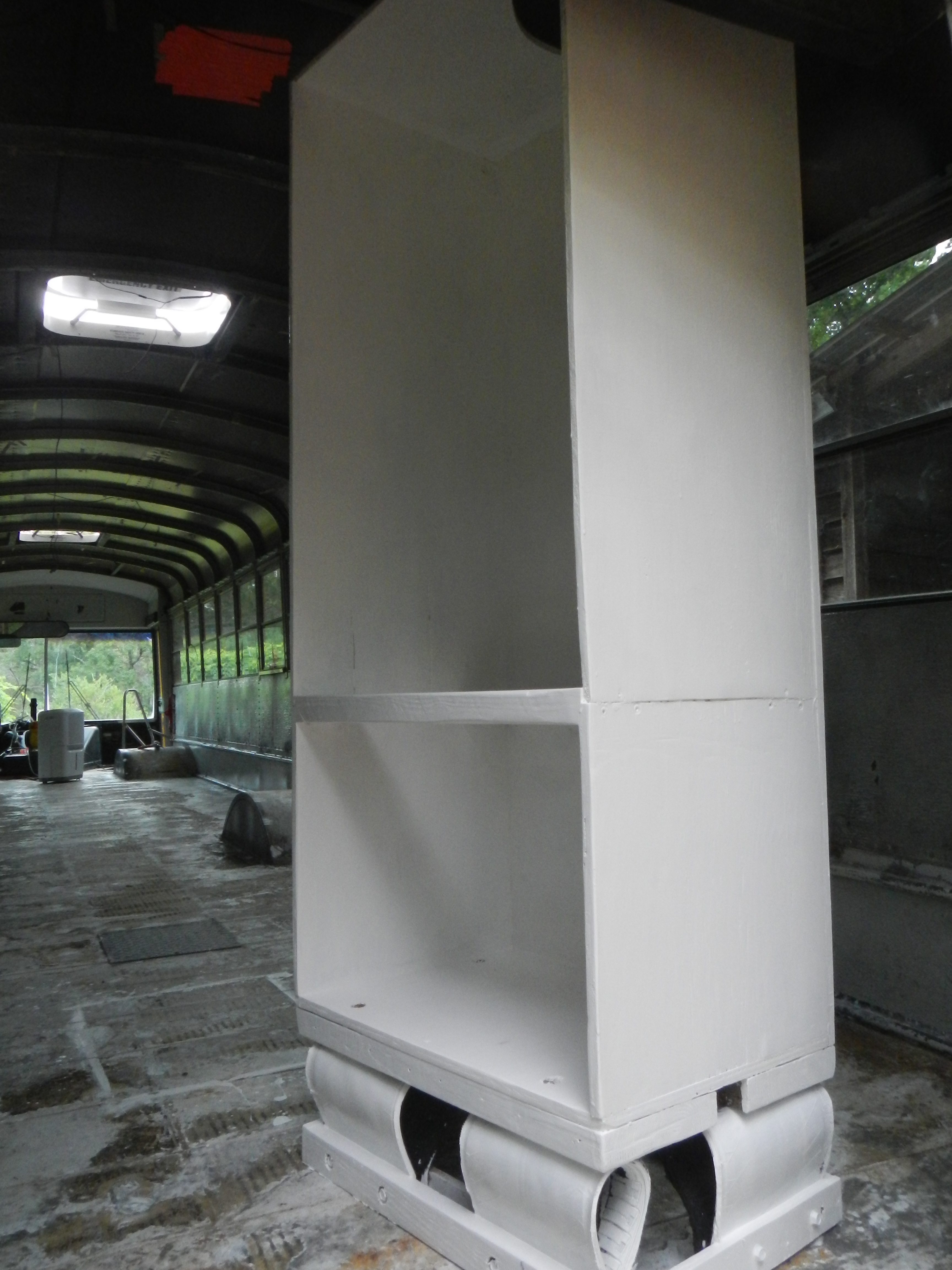
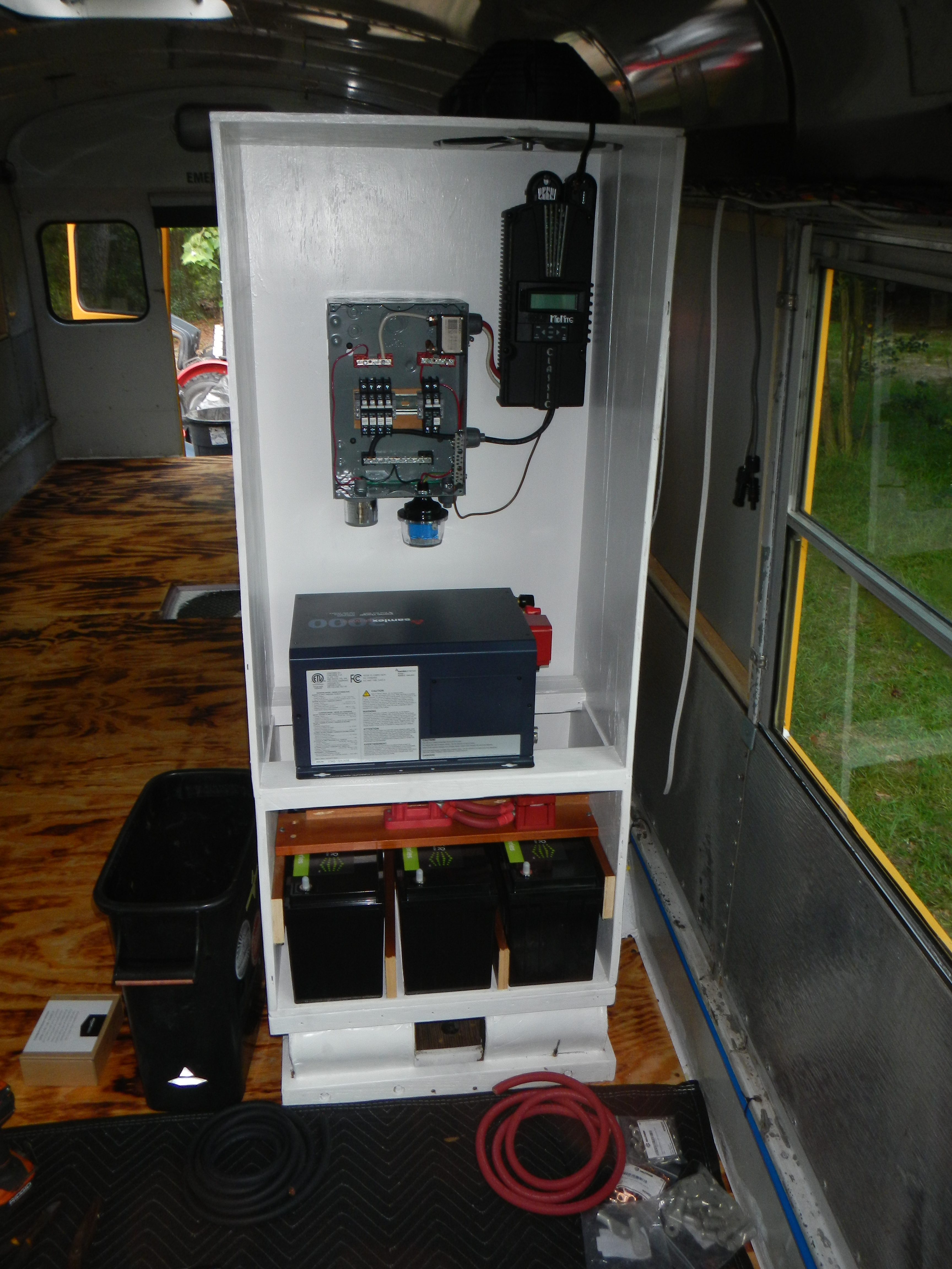
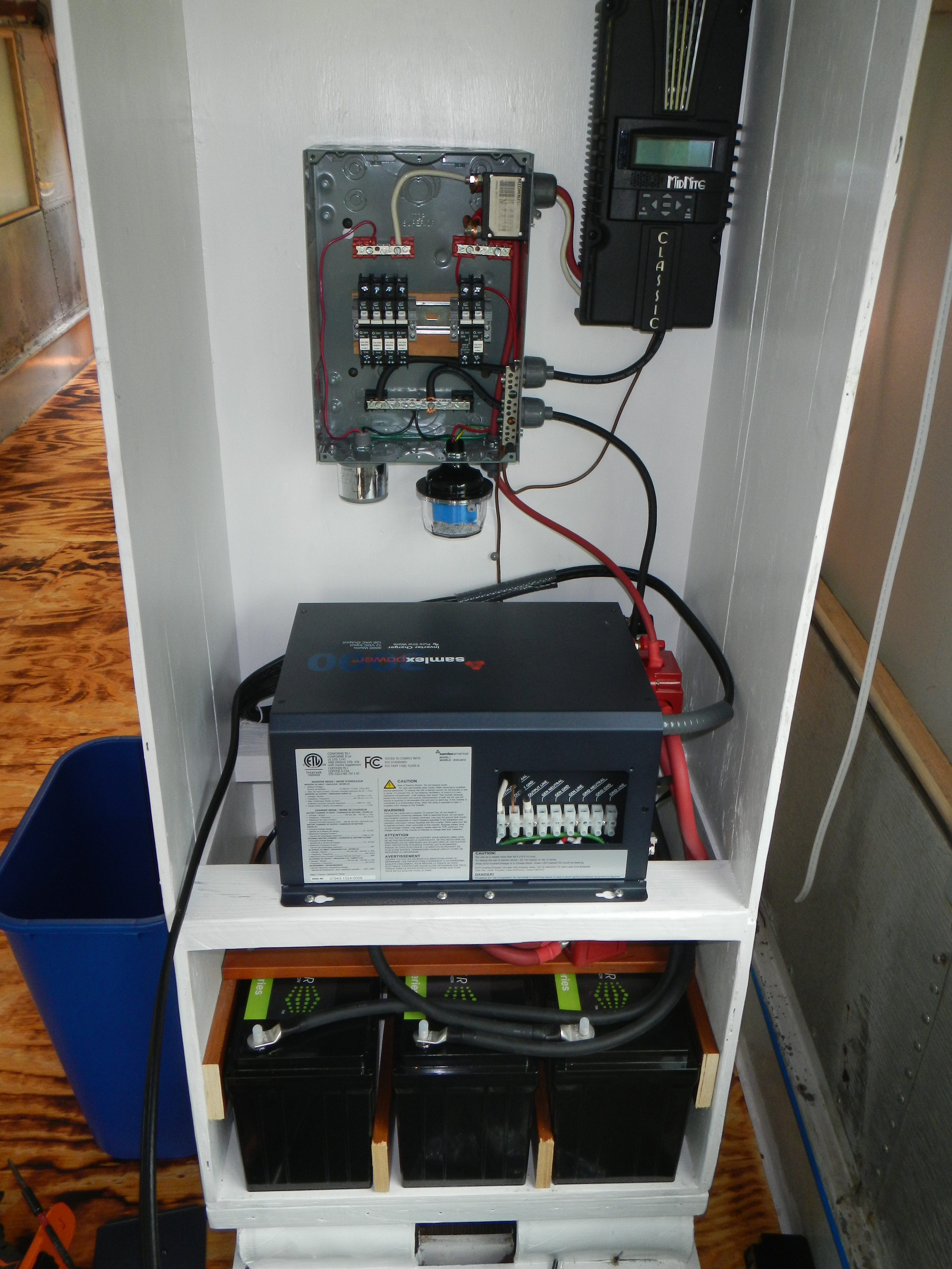
After mounting the charge controller and breaker box, I found that adding anything else would make the enclosure too heavy to easily move into the bus when the time came, so it sat on the porch for a month while I worked on the bus interior.
When the last coat of wax was buffed, Bob and Karyn helped me move the enclosure into place, after which I bolted the base to the frame of the bus (the only case so far where I have drilled through the plywood, insulation and bus floor to run bolts) and began installing hardware.
As it is now only five days (!!!) until I fly for the UK, I’ve switched focus towards preparing everything for a month of storage while I’m over with Hannah. The project will resume once I return in September.